
- The purchase order that says too little
- Step 1: read the environment
- Step 2: the cable defines the connector
- Step 3: hunt down the weak points of the circuit
- Case: the panel that changed connectors
- Specification checklist
- Splice, plug, panel or box: which type to choose
- How to read the product code
- From selection to maintenance standard
- Frequently asked questions
The purchase order that says too little
A connector specified only as “IP68, 4 poles” leaves half of its failure modes open. The requisition does not say whether the cable is 7 or 11 millimetres in diameter, whether the point is washed down with hot water, whether the motor comes off its base twice a year, or whether somewhere along the route there is a splice that nobody drew. These are exactly the variables that decide whether the seal will perform as it did in the test. When the failure shows up, months later, it is far removed from whoever placed the order and already costs much more than it would have at the design stage.
The rule of thumb known as the 1-10-100 rule sums up the problem: what costs 1 to prevent at specification costs in the order of 10 to correct at installation and 100 when it fails in operation. It is not a measurement, it is an order of magnitude, but it describes the life of an electrical connection well.
In the method Techno do Brasil presented at Mundo SENAI (detailed in the series guide), the product comes last. Before it come three steps towards a correct and durable installation: analyse the external environment, choose and harmonise the cables, and eliminate all weak points. On one of the slides the message was blunt: this “cannot be missing from the detailed design of your electrical project”. From an engineering standpoint, it is the right sequence: environment, cable, circuit, and only then the connector. It is quality at the source applied to a component that is usually treated as a storeroom item.
Step 1: read the environment before looking at the product
The first step of the Techno method lists seven agents to observe at the installation point: humidity, water, chemicals, pressure, heat, temperature variation and condensation. Each agent attacks a different mechanism: water and pressure test the seal, heat ages the elastomer, chemicals attack the polymer, and thermal cycling makes the assembly “breathe”.
- Water and pressure. Splashing, rain, hose jets, high-pressure washers or submersion are different situations, and each corresponds to a different degree of protection. The difference between IP66, IP68 and IP69K is explained in what the IP66, IP68 and IP69K ratings mean.
- Humidity and condensation. A sealed enclosure that heats up and cools down undergoes changes in internal pressure; as it cools, it draws in moist air through any micro-path, and the IP test does not reproduce this cycle. It is a separate mechanism, covered in condensation and water ingress in connections.
- Heat and temperature variation. Motors, ovens and lighting heat up and cool down in cycles. High temperature accelerates the permanent deformation of rubber, and thermal cycling causes micro-movement at the contacts. That is why the operating temperature must be checked on the data sheet of the series (T-marking), and not only against the general range of the material.
- Chemicals. Cutting oil, sanitising detergent, ammonia in cold stores, fertiliser, seawater. In the presentation, Techno showed a chemical resistance table for its materials; the subject is covered in more detail in the article on degrees of protection.
The criterion I consider decisive: describe the worst real condition at the point, not the average condition. A machine that runs dry 23 hours a day and is washed down with hot water in the last hour lives, as far as the connector is concerned, in the washdown condition.
Step 2: the cable defines the connector, not the other way round
The second step asks for four pieces of cable data: outer diameter, number of poles, cross-section of each pole and the technical specification of the cable. It looks like paperwork, but it is sealing mechanics. A cable gland seals by compressing an elastomer onto the cable sheath. With a diameter below the range, compression is insufficient and water finds its way in; above it, the seal does not close or the sheath is damaged. Then there is the effect of time: under compression and temperature, rubber undergoes permanent deformation under compression (compression set), loses its ability to recover its shape and slackens. A seal that starts out at the lower limit of compression reaches the point of leaking sooner. The degree of protection printed on the packaging only applies to the assembly mounted within these ranges.
That is why the keyword of the method is harmonise: cable and connector have to be chosen together. The conductor cross-section has to fit the terminal; the number of poles has to cover power and signal; the sheath has to withstand the same environment as the connector.
EPR or PU: the sheath material is also part of the specification
The presentation devoted a slide to cable materials. The comparison shows that the sheath must be qualified for the same environment as the connector:
| Sheath material | What Techno highlighted | Where it makes sense |
|---|---|---|
| EPR (ethylene propylene rubber) | Greater mechanical flexibility and excellent performance in water and damp locations | Underground networks, industrial installations, wet areas, panels with tight bends |
| Polyether-based PU (TPU) | Immune to hydrolysis (degradation by water), resistant to fresh and salt water, sewage, fungi and microbial attack; compatible with mineral oils, greases, solvents and weak acids and bases | Water and wastewater, oily environments, outdoor and aggressive areas |
The material also showed the corrugated conduit colour convention used in the market: yellow PVC in walls, orange PVC in slabs and floors, and black HDPE, with UV protection, in outdoor areas. A video cited in the presentation helps to visualise the difference in behaviour between cable materials.
Step 3: hunt down the weak points in the circuit drawing
This is the step most closely linked to maintenance. Techno proposes drawing the circuit floor plan and, on it, surveying:
- the distances in metres between components;
- all cable interruptions, identified and counted;
- the type of each interruption: straight splice, T, Y or H branch, or multiple branch;
- the changes in cross-section that occur at these interruptions;
- the distances between one interruption and the next.
The reason for counting is reliability. In a circuit, cable interruptions behave as elements in series: it takes only one failure for the circuit to stop. The reliability of the whole is the product of the individual reliabilities, Rsystem = R1 × R2 × … × Rn. With 20 connections at 99% annual reliability each, the circuit comes out at 0.9920 ≈ 0.82: roughly an 18% chance of at least one failure in the year, even with individually “good” components.
The calculation shows the two levers: reduce the number of interruptions and raise the reliability of each one. That, in engineering language, is what the method calls “eliminating all weak points”. In practice, the question “how many splices are there in the outdoor lighting circuit, and where does the cross-section change?” rarely has a ready answer, and without that number there is no way to manage the risk. Cutting interruptions that add no value is also what Lean does with waste in component selection.
The drawing feeds directly into a design FMEA (DFMEA): with the interruptions numbered, each one is given severity, occurrence and detection ratings, and it becomes clear which ones deserve the highest-performance connector. It is also worth treating each interface of the connector itself as a failure mode: a separate sealing ring, a loose part and a field assembly step each have their own occurrence. The co-moulded seal Techno presented, with plastic and rubber injected together and chemical-mechanical adhesion between them, eliminates one of these interfaces and one assembly step. It is occurrence reduction by design, a poka-yoke at the source.
Case: the machine panel that changed connectors
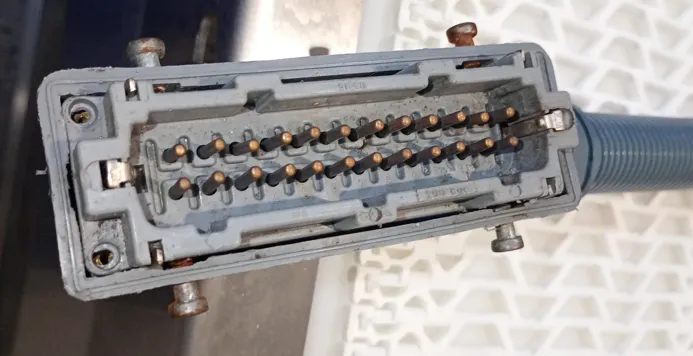
Among the cases in the presentation, the one that best illustrates the method is that of machine panels with a customised solution. The scenario: panels that used multipole rectangular connectors, like the one in the photo. The need: bring cables with different numbers of cores to the panel, with sealing and the ability to disconnect. The solution shown was to replace the rectangular connectors with circular panel connectors, chosen according to the cable of each connection:
| Cable | Connectors indicated on the slide |
|---|---|
| 12 cores | THB.406.A1E + THB.405.B2E |
| 8 cores | THB.405.A8A / THB.405.B8A + 6000087LF |
| 3 cores | THB.381.A3E / THB.381.B3E |
| 3 cores | THB.384.A1A / THB.384.B1A + 6000347LA |
The technical point of the case is the order of reasoning. The starting point was the number of cores in each cable, and from that came the combination of connector and accessory: this is step 2 of the method in practice. There is also a maintainability gain. With a disconnectable connection at the panel, replacing a module no longer requires opening the equipment and redoing terminations, which reduces mean time to repair (MTTR) by design, not by the team's effort. And each connection now has a defined code, which makes it easier to standardise stock and replacement. Other examples are collected in the cases of electrical connections in harsh environments.
Industrial connector specification checklist
Gather this information before opening the catalogue. The right-hand column indicates where the data appears in the product tables of the Techno general catalogue.
| What to survey | Why it matters | Where to check in the catalogue |
|---|---|---|
| Environment: water, jets, immersion, dust, chemicals | Defines the IP rating and the sealing materials | Technical specification tables per series |
| Minimum and maximum temperature and variation | Affects seals, condensation and service life | Temperature range and T-marking of the series |
| Circuit current and voltage | Limits the series; the catalogue lists versions from 16 A to 41 A, at voltages from 400 V to 690 V | Current and voltage columns of the product table |
| Number of poles | Power and signal may require different poles, even within the same hybrid connector | Poles header of the table |
| Conductor cross-section (mm²) | Must fit the connector terminal | Cable cross-section column |
| Cable outer diameter (mm) | Outside the range, the cable gland does not seal | Cable diameter column |
| Termination type: screw or spring | Spring needs no tools; screw accepts larger cross-sections in some series | Connection type column and code prefix |
| Function: splice, branch, plug and socket, panel | Changes the entire series | Catalogue product types (see below) |
| Connection and disconnection cycles | Equipment that is removed frequently calls for a series designed for it | Connection/disconnection cycles row in the specifications |
| Risk of condensation | May justify a version with the xDRY® anti-condensation barrier | Codes indicated in the identification guide |
| Circuit interruptions | Each one is a weak point to eliminate or specify | Circuit drawing (step 3) |
Splice, plug, panel or box: which type to choose
The catalogue organises the range by function. The question that settles the choice is simple: what happens to the cable at this point?
- Permanent splice or branch (TEETUBE® line): joins cables in line, or in T, Y or H configuration. The catalogue describes these connectors as resin-free and gel-free, re-inspectable and re-accessible, which changes life for maintenance: you can open it, look and close it again.
- Disconnectable connection (TEEPLUG® line): plug and socket for equipment that has to be moved, such as motors, sensors and modules. Versions from 2 to 8 poles are available.
- Panel connection: panel-mount versions that allow connection without opening the equipment, as in the case above.
- Junction boxes (TEEBOX® line): for distributing several points from a single one. In the presentation, TEEPLUG and TEEBOX appeared together as a low-voltage system, for both alternating and direct current.
- Co-moulded cable glands (TEEGLAND® line): secure and seal the cable entry through the enclosure.
There is also the option of a pre-wired product, with the cable already overmoulded and factory-tested; the catalogue mentions lengths from 0.5 to 5 m and custom terminal processing. For repeat batches of machines, taking assembly out of the field is a direct way of taking variation out of the process.
How to read the product code
The catalogue includes an identification guide that lets you recognise features of an item from its code alone. According to that guide:
- the prefix indicates the contact type:
THS(spring),THB(screw),THP(insulation-piercing, or piercing) andTHF(push-fit); THR.xxx.xxxorTHB.xxx.xxx.Rindicate a pre-configured product or kit;THB.xxx.Rxx,THB.Dxxx.xxxandTHB.xxx.xxx.XDindicate products with the xDRY® anti-condensation barrier;THC.xxx.xxx.xxxindicates an injection-moulded product;IoTH.xxx.xxxindicates products from the IoTH® platform.
The products available in Brazil are organised on the Techno do Brasil website into the categories of splices, disconnectables, panels and cable glands. To learn about the company and the technology as a whole, see the guide to Techno do Brasil and industrial electrical connections.
From selection to maintenance standard
A well-made specification only pays off if it becomes a standard. Three simple habits close the loop:
- Record the code of each critical connection in the CMMS, together with the cable used.
- Standardise replacement in the spare parts and MRO stock, so that the right item is on the shelf when the replacement is needed.
- Include the connection in the inspection plan, as part of the relationship between industrial connections and TPM.
And, before opening or replacing any connection, apply lockout/tagout of energy sources. If you want to compare the cost of a more careful specification with the cost of a failure, the calculation is in total cost of industrial connections, and the effect of connections on availability is covered in industrial electrical connections and productivity.
In my assessment, what sets the Techno approach apart is not any single catalogue item, but treating the connection as a system: environment, cable, interruptions, connection and validation, in that order. This is a differentiator because it addresses both variables of the series reliability calculation (how many interfaces there are and how robust each one is) while still in the design phase, which is where the 1-10-100 rule says intervention is cheapest. It is the same principle as early equipment management in TPM: maintenance prevention at the drawing board. No connector, however good, can correct a circuit that was never drawn.
Frequently asked questions
Can I choose a connector based on IP rating alone?
No. The IP rating tells you how the assembly behaves against dust and water, but current, voltage, number of poles, conductor cross-section and cable diameter must all match the series. With the cable outside the range, the seal no longer works as it did in the test.
What is the difference between a splice and a disconnectable connector?
A splice joins cables in a permanent connection, which in some lines can be reopened for inspection. A disconnectable connector uses a plug and socket and lets you remove the equipment without redoing the connection.
Why is the cable outer diameter so important?
Because the cable gland seal works by compression on the sheath. A smaller diameter leaves a gap for water; a larger diameter prevents correct closing or damages the sheath. Over time, compression set in the rubber reduces the compression, and a seal that starts at the limit is the first to leak.
What are the three steps for specifying an industrial connector?
According to the method presented by Techno do Brasil: analyse the external environment, choose and harmonise the cables, and eliminate the weak points of the circuit, with a floor plan, distances and all interruptions identified.
What is a pre-wired product?
It is a connector with the cable already overmoulded and tested at the factory. The Techno catalogue mentions lengths from 0.5 to 5 m and custom-processed terminals, which eliminates assembly in the field.
In this series
- Techno do Brasil: electrical connection technology (series guide)
- Industrial electrical connections and productivity
- How to choose industrial electrical connectors
- IP66, IP68 and IP69K: what they mean
- Condensation and water ingress in connections
- Industrial connections and TPM: reliability
- Lean and waste in component selection
- Connection cases in harsh environments
- Total cost of industrial connections (TCO)
Sources
- Techno General Catalogue (CATGENIT102024), Portuguese edition: connection types, product tables and code identification guide.
- Presentation “Complicated and Hostile Applications” (Portuguese original: “Aplicações Complicadas e Hostis”), Techno do Brasil, delivered by Mário Adinolfi on 06/11/2026 (Techno do Brasil Installation Certification Course, Mundo SENAI, Marechal Cândido Rondon/PR): three-step installation method, cable materials and machine panel case.
- Techno do Brasil: products: range available in Brazil.
- Video on cable materials cited in the presentation (YouTube).
- IEC 60529: Degrees of protection provided by enclosures (IP Code): reference standard for the IP code.
Save this address: Manufatura Enxuta is your lean manufacturing school. Come back whenever you need to study, with complete articles, a visual map and reliable sources. Follow one of the study paths or check the A–Z glossary.
Explore the technology at the source
This series explains the technology behind connections and its effect on waste. For the technical data of each item, consult the catalogue and the data sheets on the official Techno do Brasil website.
Visit the official website
About the author
Vagner Soares
Specialist in Lean Manufacturing and Behavioural Management
More than 20 years in the automotive and metalworking industries (GM and Dana), and a Lean Manufacturing specialist since 2006. SENAI instructor and mentor in the Brasil Mais Produtivo programme, with consulting, training and audits in more than 50 companies, bringing together quality, productivity and people development.


